Cisco Meraki MS120-8 Switch
Cisco Meraki MS120-48FP Switch
Cisco Meraki MS125-48FP Switch
Cisco Meraki MS125-24 Switch
Cisco Meraki MS120-48LP Switch
Cisco Meraki MS125-48 Switch
Cisco Meraki MS120-8LP Switch
Cisco Meraki MS125-24P Switch
Cisco Meraki MS125-48LP Switch

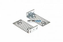
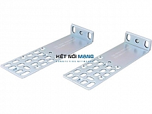
Cisco 3504 Wireless Controller Rack Mount Bracket
P/N: AIR-3504-RMNT=Cisco 3504 Wireless Controller Rack Mount Bracket
Liên hệ ngay
Cisco 3504 Wireless Controller Rack Mount Bracket
Mounting the Controller on Desktop or Shelf
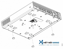
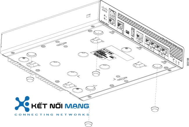
Before mounting the controller on a desktop or shelf, install the rubber feet located in accessory kit shipped with the controller.
To install the rubber feet to the controller, follow these steps:
Procedure
| Step 1 |
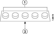
Locate the rubber feet on the black adhesive strip that is shipped with the controller. |
|
1 |
Rubber feet |
2 |
Black adhesive strip |
| Step 2 |
Place the controller upside down, on a smooth, flat surface. |
| Step 3 |
Peel off the rubber feet from the black adhesive strip and press them adhesive-side down onto the bottom four corners of the controller, see the figure below: |
| Step 4 |
Place the controller right-side up on a flat, smooth, secure surface. |
| Step 5 |
Connect the interface cables. |
Mounting the Controller on a Wall (Mounting Screws)
| Step 1 |
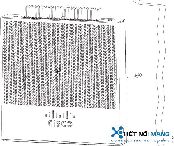
Mark the location of the mounting screws on the wall. Use the mount hole locations on the back of the controller for placement of the mounting screws. |
||
| Step 2 |
Use a 0.107-inch (2.7mm) or #32 drill bit to drill a 3/4 inch (19mm) hole for the two mounting screws. |
||
| Step 3 |
Insert two screws into the screw holes and tighten until the top of the screws are 1/8 inch from the wall (leaving enough room for the back panel to slide onto the screws firmly). |
||
| Step 4 |
Place the controller onto the mounting screws and slide it down until it lock into place, as shown in figure below:
|
| Step 5 |
After the controller is mounted on the wall, perform the following tasks to complete the installation
|
| Step 6 |
For configuration instructions about using the CLI setup program, see the (Link to Running the Bootup script section). |
Rack Mounting the Controller
To mount the controller in a 19-inch equipment rack, you can order an optional Optional Rack Mount kit (AIR-CT3504-RMNT= Cisco 3504 Wireless Controller Rack Mount Tray).
The rack-mount tray is designed for tool-less assembly. To rack-mount the controller, perform the following steps:
Procedure
| Step 1 |
Remove the four rubber feet if previously installed. |
| Step 2 |
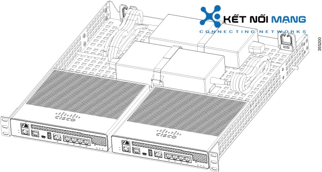
Slide the Cisco 3504 Wireless Controller in position such that the 4-tray tabs align and latch into the bottom of the unit as it is pushed in place. The front of the Cisco 3504 Wireless Controller should be flush against the front edge of the tray. A nylon latch in the center of the tray snaps into and locks the Cisco 3504 Wireless Controller in place. |
| Step 3 |
Place the power adapters between either of the two tabs in the rear of the tray and use the provided velcro straps to secure them. |
| Step 4 |
Route the AC wiring through the cable management clips. |
| Step 5 |
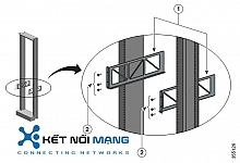
Attach the rack mount tray to the rack using the supplied screws, as shown in figure below: |
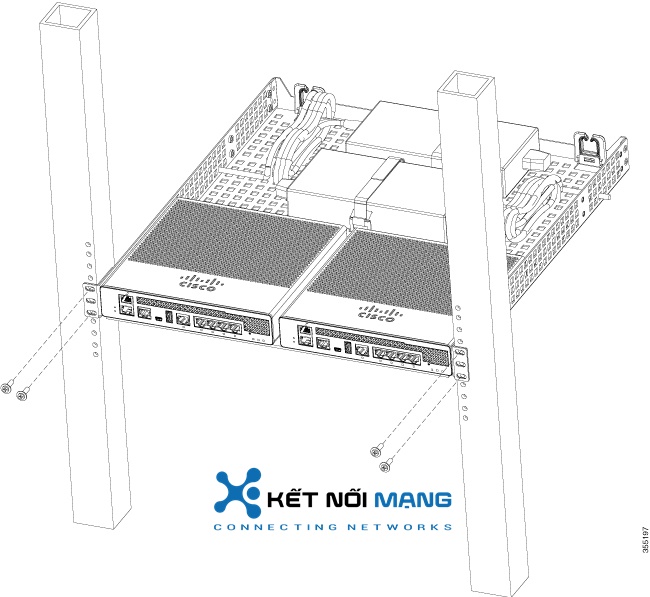
|
To remove the chassis from the rack, remove the screws that attach the chassis to the rack, and then remove the chassis. |
|
| Step 6 |
If required, install rear rack mount braces for additional stability. Include optional orderable rear rack mount adapter kit: 53-3544-05 ACCKIT, SPARE PART, RKMNT, REAR, C4948E(-F). Reuse 69-2237-05 or later, MECHKIT, ACCY,RKMNT, REAR, C4948E(-F) (or equivalent) mounting adapters to provide additional rear tray support when rack mounted in standard or deep 4-post rack. |
Sản phẩm xem thêm
Cisco Catalyst 9400 Series 4 slot chassis 19 Inch Rack Mount
Cisco Catalyst 9400 Series 4 slot chassis 19 Inch Rack Mount
Cisco Catalyst 9800 Series Wireless Controller Rack Mount Bracket
Cisco Catalyst 9800 Series Wireless Controller Rack Mount Bracket
Rack Mount Kit for 1RU for 2960-X, 2960-XR and 2960-L
Rack Mount Kit for 1RU for 2960-X, 2960-XR and 2960-L
RECESSED 1RU RACK MOUNT FOR 2960X, 2960-XR and 2960-L
RECESSED 1RU RACK MOUNT FOR 2960X, 2960-XR and 2960-L
Chủ sở hữu Website thietbicisco.vn thuộc về:
CÔNG TY TRÁCH NHIỆM HỮU HẠN THƯƠNG MẠI DỊCH VỤ KẾT NỐI MẠNG
Tên quốc tế: KET NOI MANG SERVICE TRADING COMPANY LIMITED
Tên viết tắt: KET NOI MANG SERVICE TRADING CO.,LTD
Số chứng nhận ĐKKD: 0314815571
Ngày cấp: 03/01/2018, nơi cấp: Sở KH & ĐT TPHCM
Người đại diện: VĂN NHẬT TÂN
Địa chỉ: Số 36/34 Đường Nguyễn Gia Trí, Phường Thạnh Mỹ Tây, Thành phố Hồ Chí Minh, Việt Nam
Địa chỉ giao dịch: 1061 Phạm Văn Đồng, Phường Linh Xuân, Thành phố Hồ Chí Minh, Việt Nam
Điện thoại: 84.028.35125568
Hotline: 09 014 014 86
Website: ketnoimang.vn | thietbifortinet.vn | thietbicisco.vn | knmrack.vn | alocafe.vn
Email: sales@ketnoimang.vn


